by Lee Hart, with modifications by Cor Van de Water
 |
Minimalist Battery Regulators by Lee Hart, with modifications by Cor Van de Water |
With flooded batteries, you can safely equalize by overcharging a bit - the batteries just use more water. However, you can't overcharge valve regulated (sealed) batteries the same way.
Lee Hart designed these simple, inexpensive bypass regulators to help prevent battery imbalance. They'll help flooded batteries too, but Lee mainly meant them for valve regulated batteries.
Lee says, "There are hundreds of EVs out there with [these regulators]. It's one of those KISS (Keep It Simple, Stupid) designs that no one could make money from, because it's too easy to make yourself. The whole idea was to provide a budget battery regulator, so even cheapskates wouldn't have an excuse to murder their battery packs because a real BMS (battery management system) would cost them too much."
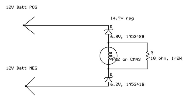
How They Work: These regulators use a #PR2 lamp (0.5 amp flashlight bulb) as the current limiter. I chose the zeners shown so they begin to bypass as soon as the battery goes above a float voltage and you are into the finishing or equalizing phase of your charging cycle. The batteries are likely to spend hours in this region as they are slowly brought from 80% to 100% SOC.
I use a lamp rather than a resistor because lamps behave more like a current source. The PR2 lamp draws 0.5amp at 2.38v, but 0.2amp at 0.238v. In other words, a 10:1 change in voltage only causes a little more than 2:1 change in current. Although the lamps aren't likely to ever burn out - they spend most of the time off or very dim - a lamp could get broken or otherwise fail. So I add a 10 ohm resistor in parallel with the lamp. If something happens to the lamp, the regulator will still work, though not as well.
I use two zeners rather than one for several reasons.
These regulators draw essentially zero current (less than 1ma) below 13v, so they won't run down a fully charged battery no matter how long you leave them connected. They only conduct when you are charging and the voltage is high.
The whole idea of these regulators is that they don't suddenly switch on at some voltage (i.e. try to reduce the charge rate of the fullest battery to zero). Instead, they gradually taper on as the battery voltage rises above the gassing point. The battery that gets there first starts having some of its charging current bypassed, so it is getting fewer amp-hours. The less-charged batteries keep getting 100% of the current you are applying.
As a rule, the voltage goes above float voltage (13.2 to 13.8v, depending on the battery's design) when the battery is about 60-80% charged. You then keep charging it for several hours, until the current falls to 2%-4% of its amphour capacity. During this time, these regulators are creating up to a 0.5amp difference in charging currents between batteries. Two hours at 0.5a is 1amp-hour, so they can compensate for a difference of 1ah or so between batteries.
This has so far been fine for good batteries in reasonable condition; it is enough to hold them in balance. But if your pack were seriously out of balance, you'd have to set your charger for a lower float voltage, and leave it on for days. Then these regulators would eventually nudge the batteries back to the same voltage.
These regulators can only bypass up to 500ma. They can't do much if the charger insists on continuing to charge at high current at high voltage. For them to balance the battery pack properly, you need some mechanism to get the charger below 1 amp when the pack is fully charged.
To do that, I use an inexpensive children's night light to sense light inside the battery box. It operates a relay to turn the charger off. It could also be set up to reduce the charger output to a very low level.
If you don't have any way to shut off or slow down the charger, use CM43 lamps instead of PR2 lamps. A #43 is a tougher part, and will last longer if the regulators are forced to run at higher currents and for longer periods of time.

Note 2: CM43 lamps cost about 75% more than PR2 lamps, but are more rugged. See the paragraph just above
the schematic to decide which you should use.
Assembly:
At 15.6v and 500ma, each zener has about 7v across it. 7v x 0.5a = 3.4 watts, which is OK for a 5w zener. The lamp has 15.6v - (2 x 7v) = 1.6v across it, which is fine for a 2.38v lamp. You need to exceed 16.6v to reach rated voltage on the lamp and 5w on the zener.
With one 6.2v and one 6.8v zener, reduce the voltages by 0.6v. With two 6.2v zeners, reduce the voltages by 1.2v.
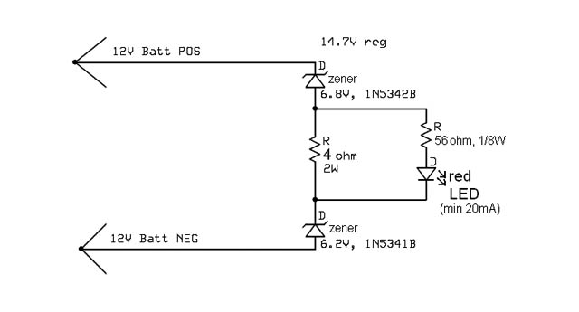
Modification: Cor Van de Water's design (below) replaces the lamp and 10 ohm, 1/2 Watt resistor with a 4 ohm, 2 Watt resistor; a 56 ohm, 1/8 watt resistor; and an LED. This eliminates the risk of damage or burnout to the lamp, at the expense of losing the lamp's more nearly constant current characteristics. Cor says this makes the design more robust and will help to avoid possible battery damage in the event of a lamp failure.
On the failure of any component, the circuit stops drawing current from the battery to avoid draining it. Should a zener diode fail shorted, the resistors will act as fuses and open to prevent fire hazard.
